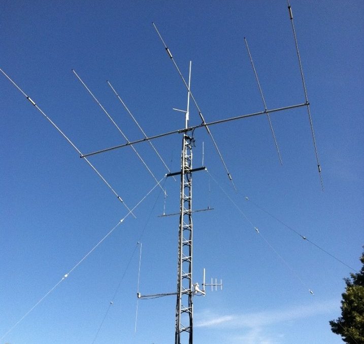
I’m not one to be ‘casual’ about technical specifics, but once they all come together, when you see what they ultimately represent – is it 1 or is it 3 S-units? – you get some idea what to stress over… or NOT!!! Other more senior and actual engineers cover the nuances MUCH MUCH MUCH better than this intro/summary – but this gets you in a direction of discovery and reality.
I always respect respectful, factual correction, and adjust accordingly. We all learn!
Our best example of a (Kirchoff’s) “law-abiding” antenna is the half-wave dipole – a ubiquitous/common standard reference. First, when we say a half-wave dipole, it’s assumed that it’s 1/4 wavelength on each side, resonant at some frequency, preferably one we want to and will operate on. Those *other* half-wave ‘dipoles’ may have two poles, but I digress… or not.
Let’s pick 20 meters, so each half of the antenna has ~16 foot wires. We’ll also set some typical assumptions that a half-wave dipole is said to present about 70 ohms impedance, and we’re feeding this with coaxial cable (50 ohm design impedance… more about that little difference later…)
If we apply what we intend to be 100 watts of power (power doesn’t exist until there is voltage AND current) – we’re applying 70 volts to a feedline. By Ohm’s Law (another law… sheesh!) current = voltage/resistance, we should be drawing 1 ampere. That means 1 ampere should be flowing via the center conductor, through/across one half of the antenna, the RF wave should bring that back to the other half of the antenna, so 1 amp should flow through/across it, and back to the transmitter on through the coax shield. Perfect!
There are or will be a couple of problems apparent with this setup. One is that we’re using a 50 ohm transmitter output stage feeding 50 ohm cable, feeding a ~70 ohm antenna. We’re going to have a tiny tiny mismatch and likely some measured/apparent VSWR at the transmitter end. If we make the antenna an inverted-V it’s impedance drops slightly and we have a better impedance match with little or no change in resonance, but our RF wave pattern may be a bit distorted. Almost everyone will (or should) reveal that a VSWR of 2:1 or less is NOTHING to *~*STRESS*~* about. Seriously – that makes LESS than 1 S-unit of difference to a receiving station… you ‘got’ this – CHILL !!!
Another is, this ‘ideal’ circumstance works best for only the one frequency the wires are cut/resonant for. Above or below that specific frequency the RF wave pattern will shift slightly and our current in each side will decrease, and as a result so will the amount of power in the circuit – and a bit less radiated by the antenna. Relax – you probably haven’t dropped that not-critical 1 S-unit…
This is the purest, simplest construct of getting RF from transmitter, to antenna, “into the air” and magically coupled to someone else’s antenna to receive it.
The half-wave dipole and a proper 1/4-wave ground plane, apart from radiated wave polarity and shape, offer the best examples of antennas complying with the laws of electrons. This is pretty easy to ‘visualize’ and measure. When we get to less-than-equal antenna parts, the RF wave and current flow behave quite differently.
FWIW – the same principle applies to balanced line feeds – and then we have different impedance concerns between 150, 300, 450, 600 ohm ‘ladder’ line and a 70 ohm dipole… maybe later…
OK – baluns? In a clean resonant system you could apply either a voltage or a current balun, but that’s a much more complex topic to be researched. RFI in this case – should NOT be an issue – but let’s see where it will be in Part 3…
