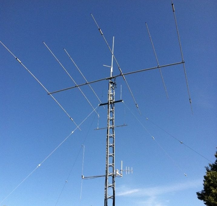
In the context of understanding and optimizing antenna systems we’ve been following the voltage and current paths of RF in two basic reference antenna types – the half-wave dipole and the quarter-wave vertical. In both of these we’ve probably assumed that we have a very direct, solid connection for the radiating element and the counterpoise element(s).
In fact is is hard to imagine that we wouldn’t have such a direct connection with a dipole – the feedline with or without balun connects directly to each wire respectively. Similarly a directly connected vertical/ground-plane antenna – with the radials/counterpoise being connected directly to a bracket where the coax connector is mounted, or a direct hole-in-body mobile mount the shield is mechanically attached to the vehicle body. Direct feedline-to-antenna constructs are fairly obvious, but we’re not always so fortunate.
Less-Than-Ideal Antenna Constructs
With various portable and HF mobile antenna installations it’s really not physically practical or prudent to try to support the bulk of an HF antenna with a mere 1/2- or 3/4-inch mobile mount in a metal surface. For this we resort to various larger mechanical mounts – ‘lip’ clamps around the edge of a trunk or hood surface, or brackets bolted to body, truck bed or frame areas.
The ‘lip’ mounts offer VERY poor connection of the coax shield current-return feedpoint to the overall vehicle surfaces – typically only two #6, #8 or #10 screws with small points at the tip intended to penetrate paint and glues to contact metal. Considering this carefully it is realized that contact is about as robust at two 18- or 20-gauge wires. Certainly not what would be suitable to carry 100-watts of RF power – a very weak point for proper RF current return. Keep this in mind as Compromise #1.
Similarly, consider the area of a vehicle hatch, hood, trunk-lid or roof – perhaps 4-6 feet maximum length, in but one direction. Just enough for a 1/4-wave counterpoise at 6 meters, but far too small for 10 meters down to 80 meters. “But the trunk/hood is connected to the rest of the body!” – IS IT? Probably NOT!!!
Inspect your body/hatch-door/hood/trunk-lid assemblies carefully. You’ll probably notice a significant amount of irregular ‘oozing’ of paint, caulking/glue, perhaps if you’re lucky a spot-weld dimple. The hatch-door/trunk-lid and hood are two halves of two separate metal shell pieces glued and crimped together – a very efficient manufacturing process that allows for some flexing, stress relief and quieting as the vehicle rumbles down the road, but LOUSY in terms of being a desirable RF electrical surface.
Similarly inspect how the trunk-lid/hatch/hood are attached to the body/chassis – hinges – also not a contiguous metal/electrical connection. Your trunk-lid/hood/hatchback are probably floating at least a few varying Ohms electrical difference from the other, larger vehicle body panels. This is a very significant factor in any/all aspects of RF when it comes to current return, stray RF, and signal radiation efficiency
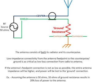
This is a good point to call-out the magnetic antenna mounts which have NO electrical connection to the intended counterpoise surface – instead relying only on very little capacitive coupling. My source of most-relevant calculations seems to have vanished off the Interwebs, but the ‘numbers’ suggest a mere 200pf or less of capacitive coupling, resulting in ~2 ohms of coupling at UHF, 6-8 ohms at hi-VHF, 12-20 ohms at lo-VHF. At ‘low’ power levels, say 20-30 watts this amount of imperfect-coupling is not too significant in terms of mis-match/VSWR, stray RF, but with such a high (25-50%) resistance at low-VHF you really don’t want to try this for 6 meters. 4-watts for CB at 27 MHz – “who cares?” With 70 RF volts at 100 watts you could have 15-30v of floating voltage between the coax and the body – that just doesn’t make good electrical or RF sense to operate with.
What you hope is a tolerable 40-60 ohms of impedance at your radio could easily be adversely affected by and additional 20 or more ohms of unwanted high feedpoint impedance. None of this changes the resonance of the antenna per-se, but it changes the impedance match your transmitter needs. Further, voltage, thus power lost to elevated feedpoint impedance means less power radiated by the intended antenna system.
With that ‘picture’ of the antenna feedpoint floating “several ohms away” from our hopeful counterpoise… a bit of illustration…
We need to accomplish two things:
- get the feedpoint/counterpoise impedance as LOW as possible across as many parts of the immediate and adjacent metal as possible
- increase the effective counterpoise surface area to provide as good RF return counterpoise as possible
While “getting the entire vehicle ‘grounded'” will help the direct RF electrical effectiveness of the vehicle body, chassis and frame, it’s obvious that’s not enough metal to ‘counterpoise’ 40 or 80 meters. At these lower frequencies we’re trying to achieve ground-effect coupling – the capacitive coupling that would come from a big rolling “magnet mount” along the road/Earth surface. NOT optimal, not very efficient, but it’s all we have.
The feedpoint coupling to counterpoise surface is not just a matter of robust wire and low DC resistance, but low RF reactance. While 12-, 10-, 8-, 6-gauge wire can handle a lot of current at DC and 60 Hz AC, the surface area is small for and presents reactance (resistance) for RF frequencies. For this reason wide strapping material is preferred – at least 1/2″ (multiple pieces in parallel?) or 1″ is the recommended norm. Short and wide – many places, every place.
You’re in for at least an hour’s work, possibly more. Not only is there direct benefit in improving RF transmission performance, this can have a profound effect on receiver performance – very often you will reduce or eliminate “ignition noise” from spark plugs, distributor, fuel injectors, perhaps quiet fuel pump noise, and quiet possibly effect two-way shielding from/for other electronic systems in the vehicle. What’s in the vehicle stays in your new fully- or at least better-shielded ‘box’, and the RF you project outside stays outside.
What and Where
This list might seem ‘excessive’ to some extent, but consider what we’re trying to achieve – doing the best we can to electrically ‘seal’ all of the electrical differences and openings of a “tin can” full of holes…
- 2-4 straps from engine hood/’bonnet’ to main body
- 2-4 straps from trunk-lid/rear-hatch to main body
- at least 1 strap per passenger door
- 8-12 straps around truck bed to frame
- 2-4 straps from truck bed to cabin
- 6-8 straps from cabin to frame
- 2 straps exhaust to frame – near engine and at tailpipe(s)
- fuel pump to body and frame
- if you have a tool box in truck bed, 2-4 straps, especially if antennas are attached to it
- at least one (I have 3) straps from antenna feedpoint to bed, body…
Where possible, take advantage of existing bolts and washers, making sure the surface is clean, free of paint, putty, glue, etc. At star (not split) lockwashers. Self-drilling sheet metal screws are handy for areas without existing bolts, but be sure to use a star lockwasher and a flat washer for larger surface contact area and remove paint/etc. from the surface you are attaching to.
How You’ll Know This Worked
As indicated above, receive performance should increase or at least the noise level should have dropped. On transmit, if you previously experienced any RF-squawking in entertainment systems that should be gone. Your VSWR should not change much, but you may notice that for tunable antennas, the point of minimum VSWR may shift slightly with the change in reactance/impedance. If the body of your antenna is located close the vehicle surfaces, things may have gotten a bit worse for the improved radiation at the antenna, so you may need to move the antenna 2-3 feet away from the body surfaces.
Great For The Mobile, But What About…
Here’s the best part – we’ve just gone through what we should have effected at our home stations. The mobile environment is the extreme, and anything that benefits it applies as well to home and other installations. Consider any opportunity for less-than-optimal-counterpoise and work to improve it likewise.
Portable and RV operations will benefit from the same increase in counterpoise surface area. Same for various verticals at home, whether you are using a shortened/loaded/mobile antenna or figuring out how to feed a telescoping vertical (metal tube or wire), or, gosh, that ‘great’ end-fed-half-wave – don’t be fooled, Kirchoff’s Law applies to them – they need counterpoise-love as well.
The take-away is that RF doesn’t work out so well with half-of-an-antenna, or even 3/4 of an antenna – the RF voltage you hope to turn into RF current that becomes RF power and radiated outward needs the best complete circuit you can provide. The desirable side benefits are decreased receive noise and a much better chance stray RF won’t find its way to where it shouldn’t be.